Solar Rooftop Integration on Pre-Engineered Buildings
Published: Jun 2026 • 8 min read
Related reading
Planning a project? Request a quote or explore PEB & structural steel by city.
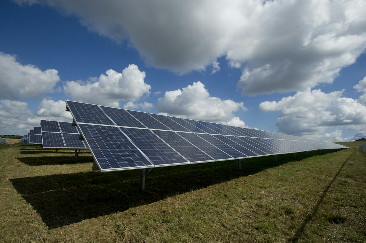
India's industrial sector is undergoing a rapid energy transition. With commercial and industrial electricity tariffs crossing ₹7–9 per unit in most Maharashtra DISCOM zones, rooftop solar on industrial sheds has moved from an optional green initiative to a core cost-reduction strategy.
Pre-engineered buildings are at the centre of this shift — their large, unobstructed roof planes make them among the most viable platforms for utility-scale rooftop solar. But the integration is not plug-and-play. A solar array imposes new structural, waterproofing, and electrical demands on the building. This guide walks through every layer of that engineering challenge.
Why PEB Structures Are Naturally Solar-Ready
The geometry of a pre-engineered building aligns remarkably well with the requirements of a rooftop solar installation. PEB roofs typically slope at 1:10 to 1:5 (roughly 5°–11°), a pitch range that suits fixed-tilt mono-crystalline panels in central India without requiring elevated racking to achieve optimal irradiance angles. More importantly, PEB construction uses long-span portal frames — clear spans of 30–60 m are standard — which means no internal columns interrupt the roof plane. A 10,000 sq.ft. roof is a single unbroken surface, unencumbered by penetrations or protrusions that would shade panels or complicate array layout.
Orientation flexibility is another structural advantage. PEB buildings can be aligned along any axis during design, so specifying a near-true-south ridge orientation during the project planning stage costs nothing and maximises lifetime energy yield by 8–12% compared to an east–west alignment.
For projects where Maxxinfra is the EPC contractor on both the building and the solar system, this coordination happens at the drawing stage — meaning no wasted money retrofitting tilt frames to compensate for a mis-oriented building.
Structural Assessment Before Installation
Before a single mounting bracket is ordered, the existing PEB must be assessed against the additional loading the solar array will impose. A standard mono-crystalline panel (400–550 Wp, aluminium frame) weighs approximately 20–25 kg. At typical packing densities, the array adds a superimposed dead load of 10–15 kg/m² to the roof. For a building designed to the minimum IS 875 (Part 1) dead load assumption, this increment can be significant.
The assessment must cover three items:
- Purlin capacity check: Cold-formed Z- or C-section purlins carry the sheeting and now also the mounting rails and panel weight. Purlin spacing (typically 1.5–2.0 m) and section modulus must be verified against the combined bending moment under the new dead load plus maintenance live load (minimum 0.75 kN/m² per IS 875 Part 2).
- Rafter and column capacity: The primary portal frames must be checked for the increased axial and bending loads under IS 800:2007 limit state combinations, particularly the gravity + wind uplift combination (1.2DL + 1.6WL) where a heavier roof can paradoxically reduce net uplift but increases compression in columns.
- Connection capacity: Purlin-to-rafter bolted connections, often M12 or M16, should be reviewed for shear under the new loads. Where the original design is found deficient, sister purlins or clip-on reinforcement channels can be added without cutting or welding the existing frame.
Maxxinfra retains structural drawings for all buildings it has erected. For third-party PEB structures, a site survey with spot thickness measurements of purlins and an as-built drawing review is the minimum starting point before committing to an installation scope.
Types of Solar Mounting Systems for PEB Roofs
Choosing the right mounting system is the single decision with the greatest impact on both structural integrity and long-term waterproofing performance. Three broad categories are used on PEB roofs in India:
- Clamp-on rib systems: Specially designed clamps grip the raised rib of trapezoidal or standing-seam sheeting without penetrating the sheet. This is the preferred system for PEB buildings — zero new holes in the roof membrane. Mid-clamps and end-clamps in aluminium alloy are rated for both compressive (panel weight) and tensile (wind uplift) loads. They suit standard Maxxinfra Maxrib and equivalent 0.5 mm+ profiled sheets.
- Penetrating rail systems with EPDM boots: Where clamp-on systems cannot achieve the required wind uplift resistance (common in Wind Zone IV and V locations per IS 875 Part 3), self-drilling screws through the sheet into the purlin flange are used. Each penetration must be sealed with a bonded EPDM grommet and a stainless-steel capping washer. This approach is reliable but demands disciplined quality control during installation and a defined resealing schedule (see Section 5).
- Ballasted systems: Concrete block-ballasted systems used on flat RCC terraces are not suitable for PEB roofs. The ballast weight (typically 15–25 kg/m²) would double the superimposed dead load on a structure not designed for it, and the inclined roof surface creates sliding risk. Ballasted systems should be excluded from any PEB solar specification.
Load Analysis: Dead, Live, Wind, and Snow Loads
IS 800:2007 requires that rooftop solar panels be treated as permanent fixtures and their weight included in the design dead load from the outset — or assessed as an imposed dead load change for retrofit installations. The structural analysis must account for all four load categories:
- Superimposed dead load (SDL): Panel weight + mounting rails + DC cabling. Typically 12–16 kg/m² over the array footprint. Apply over the full panel zone area, not averaged across the whole roof.
- Maintenance live load: IS 875 Part 2 specifies 0.75 kN/m² for inaccessible roofs with access for maintenance only. The solar array walkways (if provided) must be treated as accessible and designed for 1.5 kN/m².
- Wind uplift on panels: This is the critical load case for solar on PEB. Panels at roof edges and corners are subject to local pressure coefficients (Cpe) that can reach –2.0 under IS 875 Part 3, generating uplift forces of 1.5–2.5 kN per panel in high-wind zones. Mounting clamp pull-out capacity must be verified against these local uplift values, not just the average roof wind pressure.
- Snow and drift loads (where applicable): For installations in Nagpur and central Maharashtra, snow loads per IS 875 Part 4 are negligible. However, for PEB structures in Himachal Pradesh, Uttarakhand, or J&K, snow drift accumulation in the gaps between panel rows must be modelled — drifted snow can generate localised loads of 1.0–2.0 kN/m² that the purlin design must accommodate.
The load combination to govern design is typically: 1.2 (DL + SDL) + 1.6 WL (uplift) per IS 800:2007 Table 4, checked against both the mounting system and the underlying purlin-rafter-column chain.
One point often missed: wind pressure coefficients in IS 875 Part 3 are based on building geometry without panels. Where panels cover more than 25% of the roof area, the effective geometry changes and local pressure coefficients at panel edges should be verified against MNRE or IEC 61730 test data for the specific mounting configuration.
Waterproofing and Roof Sheet Integrity
Roof leaks are the most common complaint from industrial clients who have retrofitted solar on an existing PEB. The cause is almost always improper sealing of mounting penetrations or inadequate maintenance of existing lap joints that were already marginal before the additional foot traffic of solar installation crews.
Key waterproofing principles for solar on PEB:
- EPDM grommets at every penetration: Each self-drilling screw that passes through the sheet must use a bonded EPDM washer compressed to the correct torque (typically 8–10 Nm for M6 screws into 0.5 mm sheet). Over-torquing deforms the washer and breaks the seal; under-torquing leaves a gap. A calibrated torque screwdriver, not a standard impact driver, is mandatory.
- Sealant at panel end laps: Any point where panel end laps fall within the array zone should be resealed with a single-component polyurethane sealant (e.g., Sikaflex 11FC or equivalent) before mounting installation begins. Butyl tape applied during original construction degrades over 8–10 years and may already be compromised.
- Polyurethane roof coatings: For buildings more than five years old, a 200-micron PU coating applied across the full roof before solar installation serves two purposes: it reseals minor pinholes and lap failures, and it increases solar reflectance of the unexposed roof area, marginally improving panel temperature performance.
- Resealing schedule: All screw penetrations and lap joints within the array zone should be inspected and resealed every three years as part of the solar O&M contract. This is a contractual item Maxxinfra includes in its EPC solar scope.
Electrical and MEP Coordination
The structural and roofing scope cannot be finalised in isolation from the electrical design. Several MEP decisions directly affect how loads and penetrations are managed:
- DC cable routing: DC string cables should be routed inside metallic conduit or UV-stabilised cable trays that run parallel to purlins and rafters — never laid loose on the sheet surface where abrasion causes insulation failure. Penetrations into the building for the DC bus should be at gable walls, not through the roof sheet, to eliminate waterproofing risks at the electrical entry point.
- Earthing and bonding: All metallic mounting components — rails, clamps, panel frames — must be bonded to the primary structural steel frame and earthed per IS 3043 (Code of Practice for Earthing). The PEB frame itself, properly earthed, serves as the earthing conductor for the array. A dedicated earth electrode at each column base is the preferred configuration for large arrays exceeding 100 kWp.
- Inverter room location: String or central inverters should be located inside the building — ideally in a dedicated room at gable end — rather than mounted on the roof or outside. Indoor location protects the inverter from thermal cycling, reduces DC cable length (improving efficiency), and simplifies maintenance access. The room must have forced ventilation per the inverter manufacturer's de-rating specification.
- Lightning protection: A roof-mounted solar array significantly changes the lightning exposure of the structure. An air termination network per IS 2309 (Protection of Buildings and Allied Structures Against Lightning) must be designed for the combined building + array geometry. Air rods mounted at array corners, connected by horizontal conductors to the existing down conductors, are the standard approach.
Typical Project Timeline and ROI
To ground the above in a practical example: a 500 kWp rooftop solar installation on a 50,000 sq.ft. PEB shed in Nagpur's MIDC Butibori industrial zone follows this approximate timeline:
- Weeks 1–2: Structural assessment, load calculations, drawings submission to MSEDCL/DISCOM for net-metering approval.
- Weeks 3–4: Material procurement (panels, inverters, mounting hardware, cables). PU roof coating applied and cured.
- Weeks 5–8: Mounting system installation, panel laying, DC wiring, earthing network.
- Weeks 9–10: Inverter commissioning, AC grid connection, DISCOM inspection and metering.
- Weeks 11–12: Performance testing, O&M handover, documentation.
Total timeline: 8–12 weeks depending on DISCOM approval speed, which is the single largest variable in Maharashtra projects. Parallel-tracking structural assessment and DISCOM paperwork in weeks 1–2 is the most effective way to compress the schedule.
On the financial side, a 500 kWp system in Nagpur (solar irradiance ~5.5 kWh/m²/day) generates approximately 6.5–7 lakh units per year. At an avoided industrial tariff of ₹7/unit, the annual saving is ₹45–49 lakhs. With an installed cost of ₹2.5–3.0 crore (₹50–60/Wp at 2026 rates), the simple payback period is 5–7 years. Panel manufacturers warranty output to 80% at 25 years, meaning the system runs for 15+ years post-payback with minimal operating cost — a compelling ROI for any industrial client with a stable roof and a high grid tariff bill.
Planning a solar rooftop on your industrial building?
Our structural engineering team can assess your existing PEB or design a solar-ready structure from the ground up. Let's talk.
Get a Structural Assessment